
3C Screw Fastening: Why Torque Records Do Not Stop a Missed Screw
Most fastening stations already log driver torque, yet screws still get missed. The reason is that a torque record proves a screw was driven, not that every screw was driven. Vision monitoring adds the layer that counts and locates them.
Key takeaways
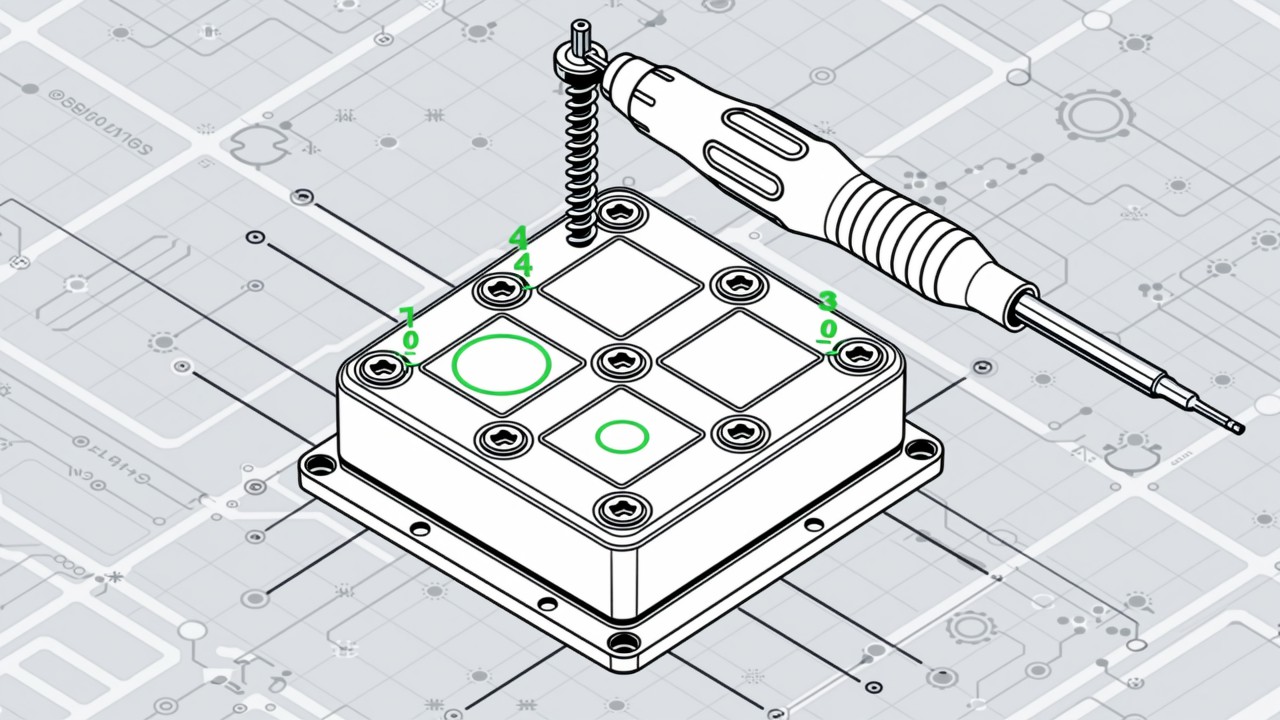
- Torque records show the total number of drives, but cannot confirm which hole each one belongs to.
- The vision targets at a fastening station are whether each hole has a screw and whether it is seated.
- Linking vision results to driver data by hole index gives a complete per-hole record.
- Highly reflective metal parts make lighting the main difficulty in this scenario.
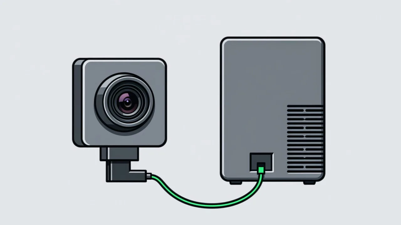
Fastening is the operation in 3C assembly that causes the most trouble and gets underestimated the most. Most lines have fitted smart drivers that log torque and run-down count, so it looks controlled. But a torque record answers how many times something was driven, not whether every hole was driven. If an operator misses one hole and drives another one twice, the total can still add up. The wider industry pattern is covered under 3C electronics assembly visual AI SOP.
Three ways a missed screw shows up
| Exception | What it looks like | Can the driver catch it? |
|---|---|---|
| Missed screw | One hole has no screw at all | Not necessarily — the total count can still reconcile |
| Double drive | The same hole driven twice | Not necessarily — the total count can still reconcile |
| Screw not seated | Driven but proud, skewed or stripped | If torque is abnormal, yes; otherwise no |
| Wrong order | Not tightened in the specified diagonal or sequence | Usually not |
How vision judgement works
The approach is to bring the hole area of the fastening station into the field of view and, once the fastening action is complete, judge whether each hole contains a screw and whether it is properly seated. Results are output by hole index and compared item by item against the product’s hole list. What you get is which screw was missed, not that the total is short. The full detail on detection granularity is in AI visual workstation SOP monitoring.
A stronger version is to link the vision result to the driver data by hole index. Drivers usually record the station and time of each rundown, and vision judges hole state at the same moment; cross-checked, the two give a complete per-hole history — when this hole was driven, at what torque, how many attempts, and its final state. That is currently the most reliable combination for this scenario, and it is also what makes the sequence check in preventing skipped steps enforceable at the hole level.
Making the picture and the torque data agree
The value of combining vision with driver data is not that either one is weak on its own, but that they disagree in useful ways. A hole the driver reports as driven but the camera sees as empty points at a mis-indexed rundown or a screw that was cross-threaded and dropped. A hole the camera sees filled with no matching torque event points at a screw placed by hand. Those two cases account for a large share of real fastening escapes, and neither system would catch them alone. The principle of judging the combined result rather than each channel separately is the same one set out under precision and recall.
Common questions about fastening stations
There are many models, each with a different screw layout. Does that mean custom development?
No. The hole layout is entered as product configuration and recalled by model at changeover. A new model only needs its hole information entered and one validation run.
The screws are tiny — can the camera see them?
Screws of M1.2 and above can usually be judged reliably at a sensible field of view. Smaller sizes need imaging validation first.
Can it tell whether a screw is tight enough?
Vision can catch obvious problems such as a screw standing proud or sitting skewed, but the degree of tightness is mainly judged from torque data. That is exactly why the two are best combined.
Missed screws at your fastening station?
Tell us the product type and screw size and we can judge the imaging feasibility.
Related articles
-
Alarm Fatigue: Why the Floor Turns the System Off
Many visual SOP systems are not beaten by technical problems — they are muted by…
Read more → -
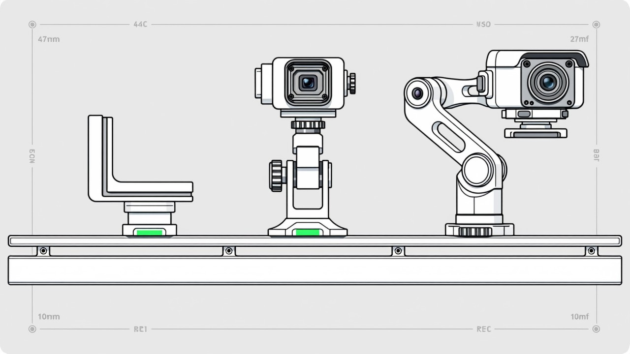
Visual SOP Camera Selection and Mounting
Camera selection for visual SOP is not the same as for product inspection. The s…
Read more → -
Vision Monitoring at the Semiconductor Die Bonder
Semiconductor packaging stations are characterised by high precision, fast cycle…
Read more → -
Wrong-Assembly Alarms Without the False Alarms
The most common reason a visual SOP project fails is not poor recognition — it i…
Read more →
Need specific advice for your production line?
Our engineers can share practical approaches to process error prevention and SOP compliance inspection for your scenario.
Request a free trial plan