
Lighting Design: Why It Affects Detection More Than the Algorithm
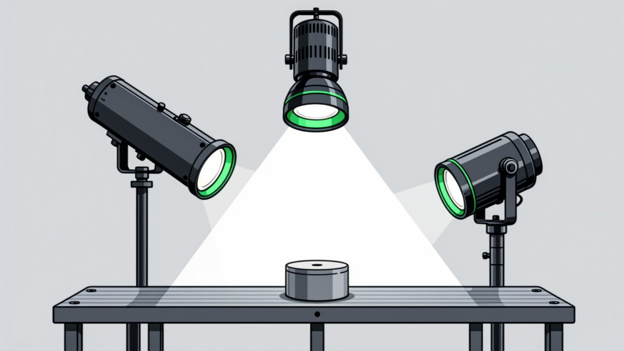
The ceiling on detection accuracy is set at the imaging stage. With the right light the judgement reduces to a simple threshold comparison; with the wrong light even a strong model is only finding patterns in noise. Good lighting design produces a stable contrast between target and background — and keeps it stable across shifts, months and ageing lamps.
Key takeaways
- Imaging sets the ceiling on accuracy; the algorithm approaches that ceiling but cannot exceed it.
- The goal of lighting is stable contrast, not brightness.
- Ambient light is the largest single variable: windows, ceiling lights and neighbouring stations all shift it.
- Mirror-finish metal, transparent parts and deep bores cannot be given stable contrast by ordinary lighting.
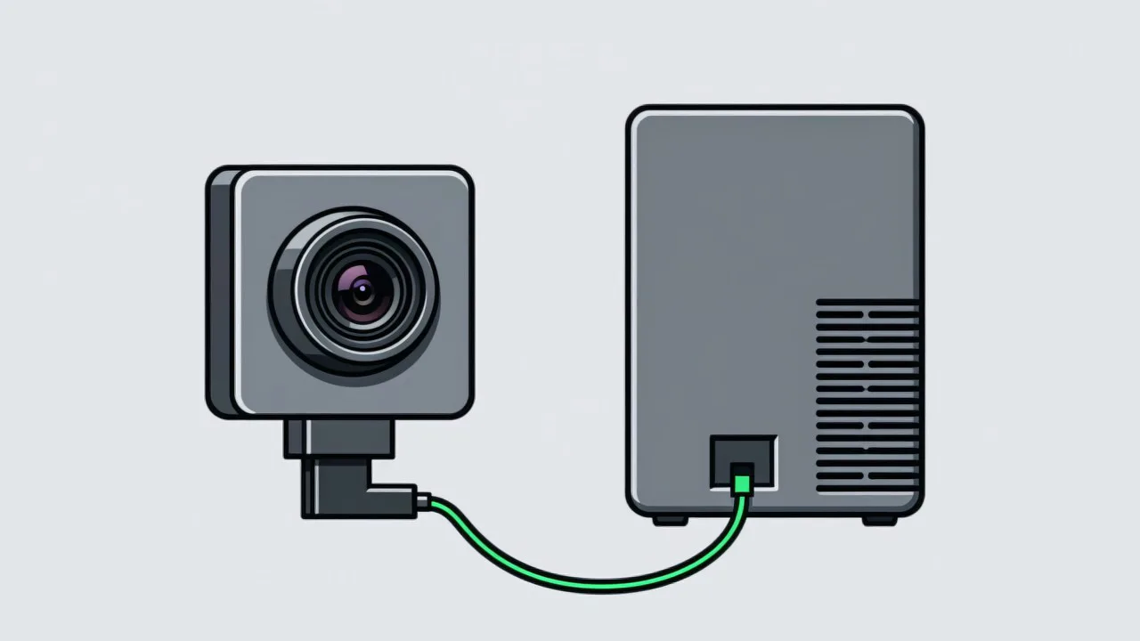
On a production vision project the ceiling on detection accuracy is set at the imaging stage. With the right light the judgement reduces to a simple threshold comparison; with the wrong light even a strong model is only finding patterns in noise. That is why the same algorithm can perform very differently at two stations that look alike — the difference is not in the algorithm but in the lighting and in how much the ambient light is controlled. Lighting deserves to be assessed as its own subject at the design stage rather than patched once the station refuses to stabilise, which is also how the imaging requirements for the Visual AI SOP System are framed.
The goal is stable contrast, not brightness
- Contrast has to be large enough. The grey-level difference between target and background should leave headroom on both sides of the threshold, so that a small lighting drift cannot flip the result.
- Contrast has to be stable. Day shift and night shift, the start and the end of a month, before and after a lens clean — the imaging should land in the same range every time.
- Contrast has to be explainable. The site needs to understand why the light is arranged this way, or the setup will be disturbed without anyone noticing when equipment moves or the station is rearranged.
- A phone photo settles more than it looks like it does. At the design stage, take a phone photo from the intended camera position and look at whether the target edge is clean, whether there are specular highlights, and whether anything in the background interferes. If the phone cannot resolve it, an industrial light may not either — which usually means the detection target itself needs rethinking.
The four basic lighting geometries
| Geometry | Light path | What it is good for |
|---|---|---|
| Bright field | Light on the same side as the lens, aimed at the target | Surface colour, markings, presence — the commonest choice |
| Dark field | Light grazing the surface at a low angle | Scratches, burrs, edge contours, surface relief |
| Backlight | Light behind the target, the lens sees a silhouette | Outline dimensions, hole positions, contour completeness |
| Coaxial | Light passes a beam splitter and travels along the lens axis | Characters and marks on reflective flat surfaces |
In practice the most common combination is a ring or bar light in bright field to judge presence, colour and position, with a backlight or side dark field added where a contour has to be judged — whether a connector is fully seated, for example. Where a rule set includes both position and contour, the two lights are often strobed alternately in sync with the exposure. That is a mechanical design decision, and software cannot make up for it. Camera position limits what lighting is possible, so the two are settled together; see camera mounting and field of view.
Ambient light is the largest variable
- The ambient light is moving while everyone blames the lamp for being too weak. Daylight through a side window changes direction and intensity through the day, ceiling lights run fully or partially at shift change, and a newly fitted light at the next station may shine straight into the lens. The resulting brightness swing is often larger than the difference the system is trying to detect.
- Shroud the lens. A hood or a simple baffle keeps the side light out. It costs very little and the effect is usually immediate.
- Make the dedicated light dominate. Once the active light supplies most of the illumination, the ambient swing is a small share of the total.
- Strobe rather than run continuously, and lock exposure and gain. Strobing only at exposure cuts heat and power and narrows the window in which ambient light matters, and it pairs with the short exposure needed for motion — the trade-off is set out in shutter type and motion blur. Leaving auto-exposure on lets ambient changes turn quietly into image changes and takes the meaning out of every threshold.
Where lighting cannot save the application
- Mirror-finish metal. On a curved metal part the specular highlight moves with the viewing angle, so the same component images very differently as its pose changes. Polarising filters and coaxial light are worth trying, but whether they work depends on surface roughness and cannot be assumed.
- Transparent parts. A transparent material neither reflects nor blocks, and its edge depends on refraction, so contrast is weak and background-dependent. These targets usually need a purpose-built backlight and diffuser, which is markedly more complex than an ordinary station.
- Deep bores. What can be seen inside a bore is limited by the ratio of diameter to depth, and ordinary lights do not reach it; a borescope or fibre-optic arrangement is required.
- Randomly textured surfaces. Castings, textiles and foamed materials have random texture, so the grey-level distributions of target and background overlap and thresholding does not apply.
- The pragmatic alternative is to change the target. Move the judgement from “surface condition” to “did the action happen” — whether a hand reached the pick position, whether the part was placed on the fixture — rather than judging surface defects. Action judgement deals with coarse position and sequence and demands far less of the imaging. This is one reason vision SOP is easier to deploy than cosmetic inspection: the two are not judging the same layer of the problem. Reducing the alarms that do occur is covered in how false alarms are reduced.
Do not overlook long-term lighting maintenance
- Output declines with age. Once the light dims, a threshold that was set with headroom drifts towards the boundary. This typically surfaces six to twelve months after go-live, and machining, moulding and dispensing stations show it first, as the practices described for auto parts illustrate.
- Lenses collect dust and oil mist. Cleaning frequency and an owner need to be written into the daily check rather than left to whoever notices.
- Station changes break the lighting. After equipment moves, a fixture change or a line modification, the light angle is often disturbed without anyone realising. A baseline image captured at acceptance should be archived so the setup can be restored against it.
Common questions about lighting
Why is lighting worth more investment than the camera or the algorithm?
Because imaging sets the ceiling on accuracy, and neither the camera nor the algorithm can exceed it. Better lighting tends to reduce the difficulty of the judgement directly, and usually returns more than a higher-resolution camera or a more complex model.
Why can the ceiling lights not simply be used?
Their position, colour temperature and output were not designed for imaging, and they change with shift and time of day. Judgement needs stable contrast, not illuminance. A dedicated light is there to make the illumination controllable and repeatable, not merely brighter.
How long does the lighting design take?
With clear station conditions it can be settled at the design stage with sample images. Where transparent or highly reflective parts have to be validated, expect one or two rounds of lighting trials of several days each. That time belongs in the project schedule and should not be compressed.
Fighting reflections that will not settle?
Send a photo of the station and describe the target, and we will suggest a lighting geometry.
Related articles
-
Alarm Fatigue: Why the Floor Turns the System Off
Many visual SOP systems are not beaten by technical problems — they are muted by…
Read more → -
Visual SOP Camera Selection and Mounting
Camera selection for visual SOP is not the same as for product inspection. The s…
Read more → -
Vision Monitoring at the Semiconductor Die Bonder
Semiconductor packaging stations are characterised by high precision, fast cycle…
Read more → -
Wrong-Assembly Alarms Without the False Alarms
The most common reason a visual SOP project fails is not poor recognition — it i…
Read more →
Need specific advice for your production line?
Our engineers can share practical approaches to process error prevention and SOP compliance inspection for your scenario.
Request a free trial plan