
Visual AI SOP for 3C Electronics Assembly Lines
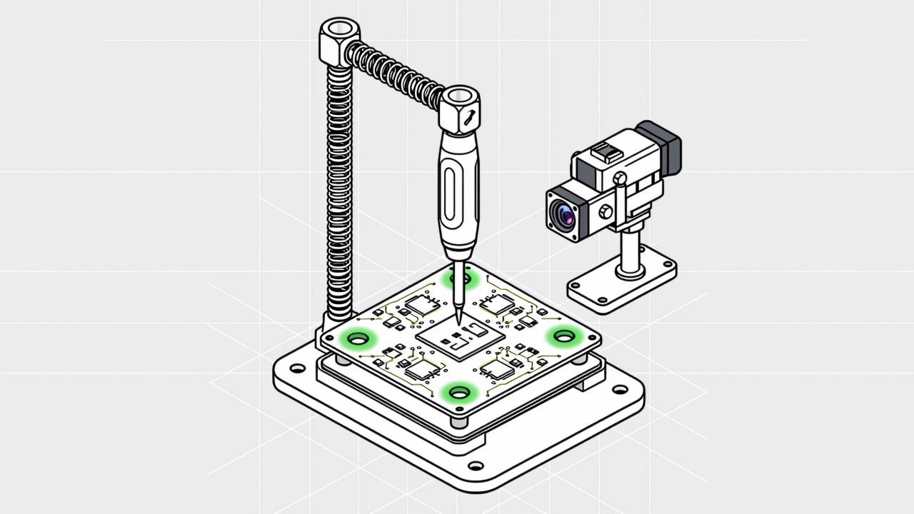
3C assembly is characterised by many small parts, many screws, tight tolerances and rapid model turnover. Assembling one laptop can involve dozens of screws in different specifications, each with its own fastening sequence and torque requirement. We deploy Visual AI SOP at fastening, lamination, sub-assembly and appearance inspection stations to verify screw count and fastening sequence in real time, stopping missed screws and wrong sequences at the workstation.
Key takeaways
- Fastening anti-omission: checks screw count and specification against the model, alarming immediately on a missed or short fastening.
- Fastening sequence verification: works with the electric screwdriver controller to confirm the actual tightening order matches the SOP.
- Lamination and sub-assembly: monitors film removal, alignment and pressing actions for step completeness.
- Model-change friendly: new models need only process parameters and counts, so recognition models are reused and adaptation is fast.
- Appearance inspection hand-off: data can be connected to existing AOI or manual appearance stations.
The classic missing step in 3C assembly is the missed screw. A single device carries many screws in mixed specifications, and after hours of repetitive motion an operator can easily skip one - a defect that usually only shows up in a drop test or in the customer's hands.
The second most common problem is wrong fastening sequence. Some products are designed to be fastened in a specific order - diagonally, or from the centre outwards - and the wrong order concentrates stress or leaves a joint unseated while nothing looks wrong from the outside. Both problems are well suited to real-time interception using workstation operation monitoring, and the method is set out in our article on 3C screw fastening monitoring. The same approach also serves small appliance assembly.
Monitoring Stations and Decision Logic
| Workstation | Monitored content | Decision basis |
|---|---|---|
| Fastening | Screw count seated, fastening sequence, screw specification differentiation | Count checked against the model; sequence compared with electric screwdriver signals |
| Lamination | Film removal, alignment and pressing actions | Completeness of the action sequence |
| Sub-assembly | Flex cable insertion, clip pressing, foam or shield placement | Presence and position of the part |
| Dispensing / spot welding | Dispense path, adhesive volume confirmation, weld points | Path coverage and point count |
| Appearance inspection | Inspection step completeness, verdict gesture, logging action | Completeness of the action sequence |
| Packing | Accessory configuration, manual placement, carton sealing action | Accessory presence and count |
Fastening Error Prevention with Tool Interlock
How fastening error prevention is implemented
- Read the model and screw BOM
Get the current model's screw count, specification and fastening sequence requirements from MES or the station terminal.
- Capture screwdriver action signals
Read the completion signal and torque verdict for each tightening event over the controller interface.
- Verify seating and order visually
Confirm which holes the screws actually landed in and in what order, comparing item by item with the SOP.
- Intercept or release
If count or order does not match, prompt at the station and hold the unit; if it matches, record and release.
Capability Boundaries on a 3C Line
Two limits are worth stating plainly. Vision confirms which hole a screw went into and in what order; the torque value itself is the driver's reading. And once a shield or bracket is fitted over the fasteners they are no longer visible, so the check belongs at the fastening station rather than at final assembly. The trade-offs between field of view, resolution and working distance are worked through in visual SOP camera selection.
- Specifications closer than the imaging resolution can resolve, such as two near-identical head types, need a narrow field of view or a cross-check against the driver's socket position.
- Screws fully hidden under a fitted cover cannot be judged after the fact.
- Very short, very fast motions need a shutter speed high enough to freeze them, which may mean raising the ambient light.
- Preconditions: a model-specific screw map, the fastening sequence, and a signal from the electric screwdriver controller.
3C electronics assembly questions we hear most
Screw specifications are very similar - how does vision tell them apart?
Mainly by head size, head type, colour and the surrounding hole context. Where the difference is below what the imaging resolution can resolve, the torque position from the screwdriver can be used as a cross-check.
Product generations turn over quickly - does the algorithm have to be rebuilt each time?
No. Action recognition models are common across models; a generational change mainly means updating screw counts, hole coordinates and sequence configuration.
The line is already crowded - is there room for cameras?
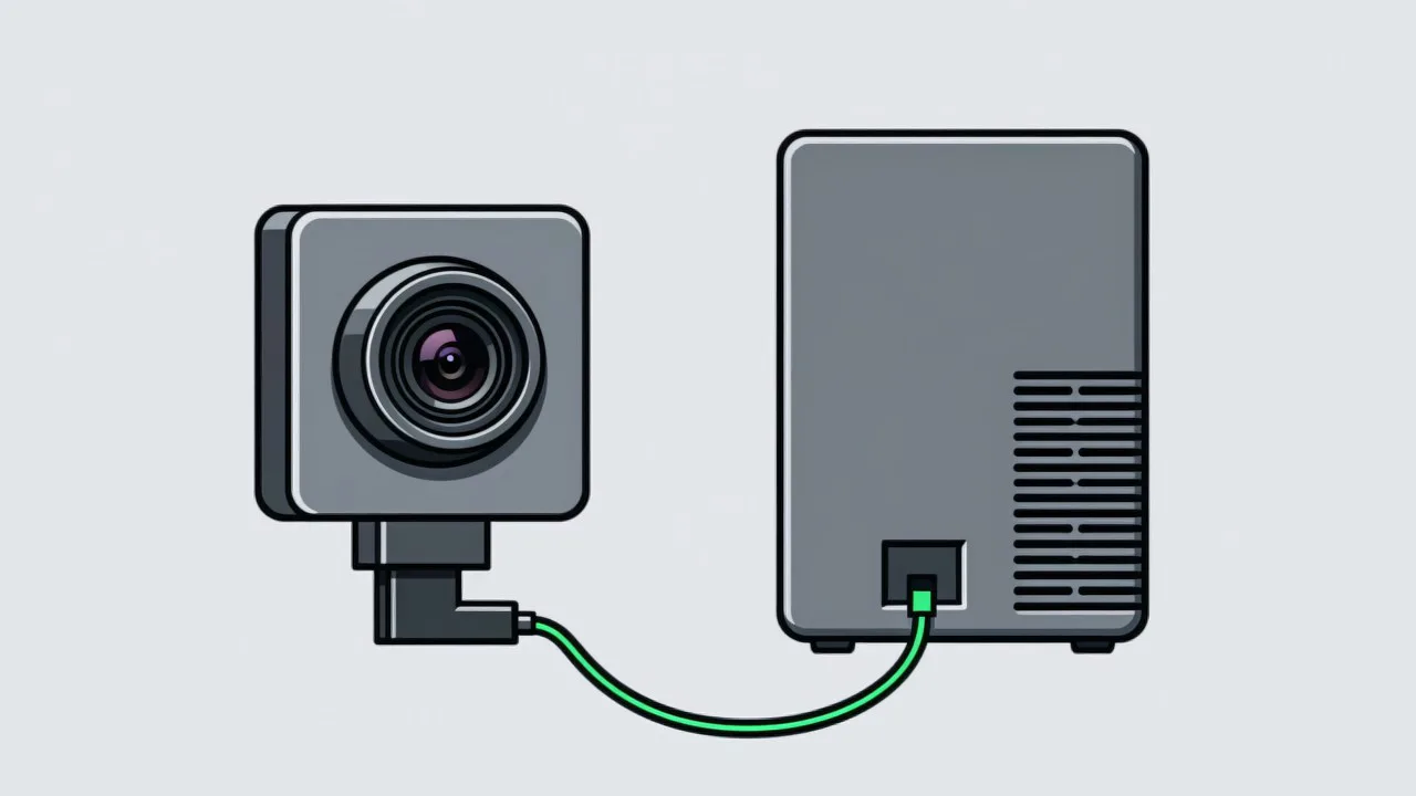
3C lines are usually tight on space. An all-in-one smart camera is an option - small, with no separate industrial PC, mounted on the beam above the station or outside the ESD curtain.
Assess your 3C assembly workstation
Tell us your workstation layout, cycle time and the process that causes the most trouble today, and we will recommend camera options and a pilot workstation.
Other industry solutions
-
Textile
Textile and apparel work splits into very fine operations and changes …
Read more → -
Food Processing
Food process management has two hard constraints: food safety audits d…
Read more → -
Small Appliances
A significant share of small-appliance field failures are not failed c…
Read more → -
Auto Parts
The typical auto parts plant runs high variety, low volume and fast ch…
Read more → -
Automotive Assembly
Final assembly is where carmakers have the densest concentration of op…
Read more → -
Semiconductor
Semiconductor packaging has a long process chain, fast station cycle t…
Read more →
Related products & capabilities
-

MES Integration
Run standalone, a visual SOP system only solves on-the-spot blocking. …
Read more → -
Error Prevention
The point of poka-yoke is to make an error impossible, or to catch it …
Read more → -
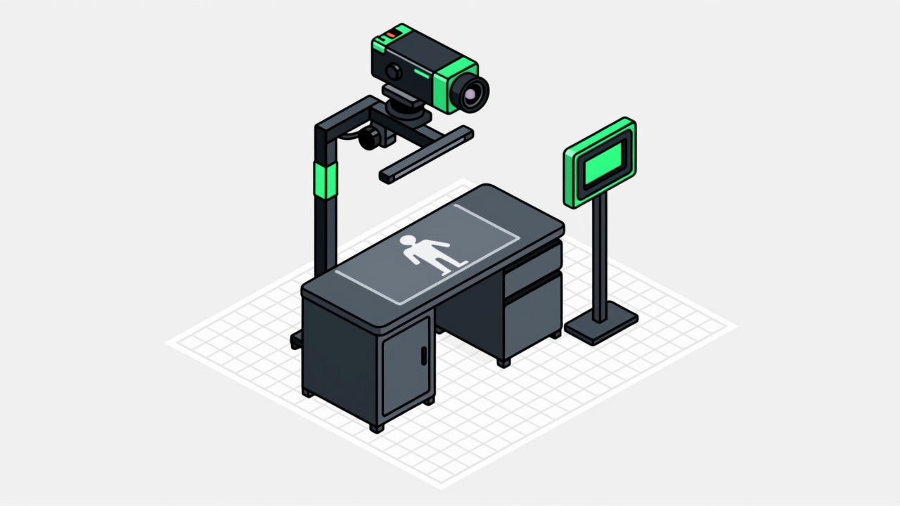
Workstation Monitoring
The workstation is the smallest unit of SOP execution. We turn the vid…
Read more → -
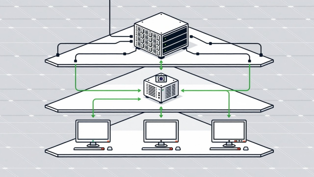
Visual AI SOP System
The Intsoft Visual AI SOP System is built in four layers: workstation …
Read more →
Does your industry face similar process problems?
Tell us your workstation scenario and process pain points, and we will tailor a solution based on cases already delivered in your industry.
Request a free trial plan