
Error-Proofing and Visual SOP on a PV Module Line
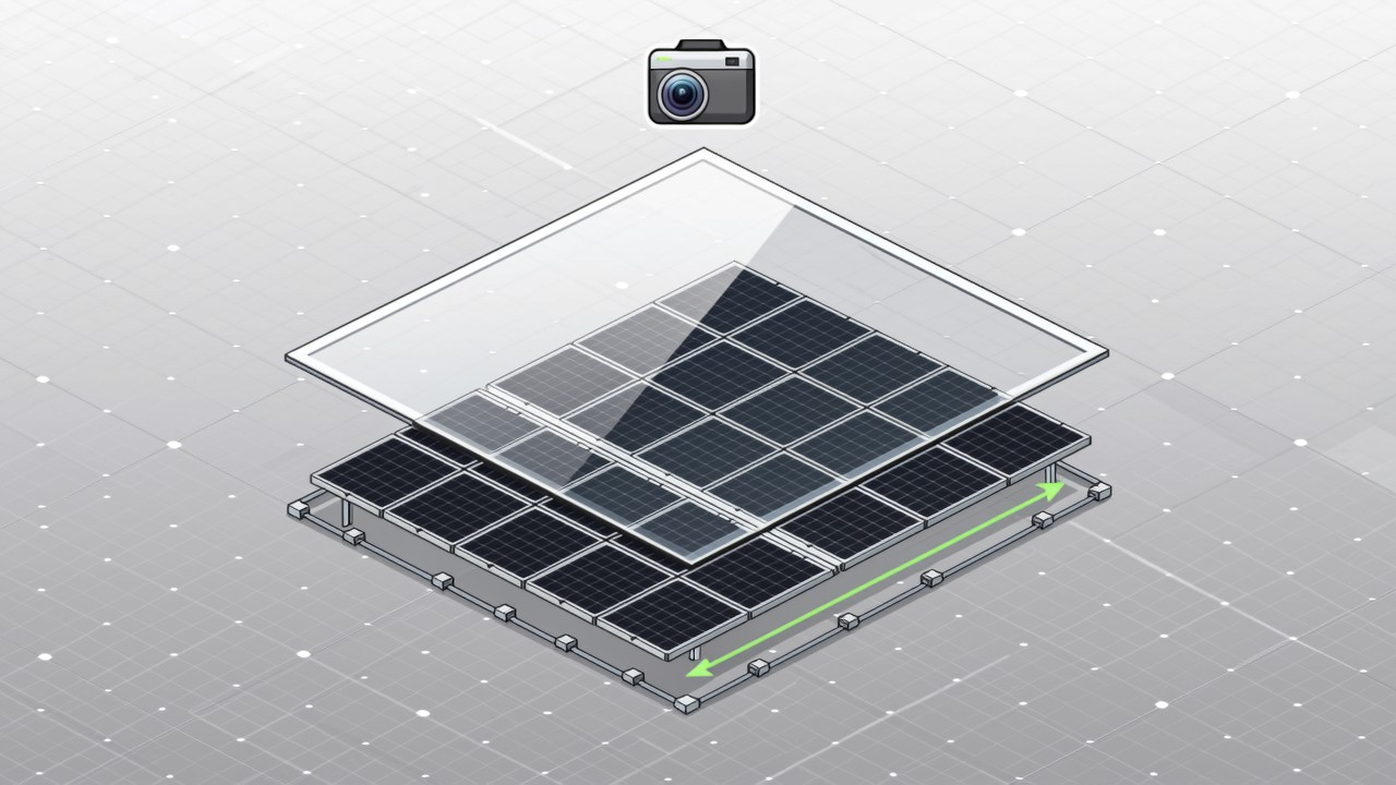
The quality risk in a PV module line sits before lamination, not at final test. Flipped glass, a missing or doubled encapsulant sheet, cells stacked in the wrong order, ribbon out of position, reversed junction box polarity — none of these can be stopped by a downstream station at the moment they happen, and once the module is laminated nothing can be reworked. A visual SOP puts the judgement point at those stations instead, confirms the stack-up and ribbon position, and writes the record back to MES. It does not replace EL or IV testing, and it cannot judge weld strength.
Key takeaways
- The stack-up and stringing section before lamination carries the highest rework cost, and moving the judgement point there is where the return is.
- Thin cells and highly reflective glass and encapsulant make the imaging problem a design decision, not something to fix after the software is installed.
- Vision can confirm order, position and presence; it cannot judge weld strength or internal micro-cracks, which belong to pull testing and EL testing.
- Stringing and lay-up stations run on a cycle of seconds, so any alarm that stops the line will be bypassed within days.
Error-proofing a PV module line is not really about the EL and IV testers at the end. It is about the stack-up and stringing section before lamination: glass placed face-down, an encapsulant sheet left out or doubled, cells laid in the wrong order, ribbon shifted off the busbar, a junction box wired with reversed polarity. None of these can be caught by a downstream station at the moment they happen, and by the time a tester finds the symptom the module has usually been laminated — there is no rework path, only downgrade or scrap. A visual SOP places the judgement point at those stations instead: a camera confirms the stack-up order, that the encapsulant is present, and where the ribbon sits relative to the cell, flags the deviation as it happens, and writes the process record back to MES. It does not replace EL or IV testing, and it does not judge weld strength.
Why the stations before lamination cost the most
A module line runs roughly: cell sorting, tabbing and stringing, lay-up, lamination, trimming, frame fitting, junction box, curing, cleaning, EL and IV test, packing. Lamination is the dividing line. It presses glass, encapsulant, cell strings and backsheet into one body, and after that no internal position can be adjusted again. Every station before lamination is still correctable; every station after it can only inspect. That boundary is what should decide where the error-proofing budget goes.
- Stringing. Ribbon-to-busbar alignment, ribbon shifted or lifted. A shift outside the process window creates a cold-joint risk that only shows up under EL.
- Lay-up and stack-up. Glass orientation, whether the encapsulant sheet is missing or doubled, the order and spacing of cell strings, busbar position. Getting this wrong is the most expensive mistake on the line.
- Framing and junction box. Frame fitted the wrong way up, positive and negative leads swapped, insufficient or misplaced sealant.
- Appearance. Cell micro-cracks, chipped edges, flux residue on ribbon, scratched glass. Visual inspection only catches a share of this.
The imaging limits of thin cells and reflective materials
The optics on a module line are harder than most. Cells are commonly in the hundred-micron thickness range, so a small error in a suction cup or robot position can chip an edge. Glass is a mirror: mount a camera facing it and the frame fills with reflections of the light source and the surrounding cell. Encapsulant is semi-transparent, so distinguishing one sheet from two under ordinary lighting is difficult. Ribbon is a narrow metal strip with low contrast against a silver-white busbar. The imaging concept therefore has to be settled early in the project, not tuned after the software goes live. For how to light transparent and reflective targets, see lighting design for visual SOP; the shared constraints of thin, high-precision work are discussed for semiconductor processes.
| Target | Imaging difficulty | Common approach |
|---|---|---|
| Glass orientation | Both faces look almost identical in visible light; the difference is at the edge | Grazing side light on the chamfer and print, or a sequence check against incoming orientation |
| Encapsulant present | Semi-transparent; one sheet and two differ little in brightness | Backlight or a narrow-band transmission setup to amplify the single-double difference |
| Ribbon position | Narrow metal strip, silver-white against a silver-white busbar | Low-angle bar light to raise edge contrast; convert pixel distance to offset |
| Junction box polarity | Similar wire colours, partially occluded | Fixed view reading wire order and marking, judged against assembly sequence |
Cycle time and alarms decide whether it survives
Stringing and lay-up run on a cycle measured in seconds; a station may have two or three seconds to complete its action on one cell. At that pace the shape of the alarm matters more than recognition accuracy. A modal dialog that must be dismissed before work continues gets bypassed after a few hundred repetitions; a prompt that arrives seconds late is no prompt at all. A more workable convention is two alarm levels — sequencing errors such as a missing encapsulant sheet stop the station and require action, while position deviations are recorded and flagged for the process engineer to judge. The trade-off between thresholds that miss and thresholds that nag is covered in more detail under reducing false alarms.
Where to run the first trial
Starting with a whole section is not advisable. Pick one station where the action repeats, the position is fixed and the consequence of failure is unambiguous — stack-up order confirmation and junction box polarity are usually better first stations than ribbon alignment, because the target is easier to define and less arguable. Prove miss rate and false-alarm rate on real production data before copying to similar stations. To judge whether a station is ready, work through the visual SOP site assessment checklist; if several similar stations are moving at once, the lessons in pilot success, rollout failure are worth reading first.
Common questions on PV module inspection
Can visual inspection replace EL testing?
No. EL testing uses electroluminescence to reveal micro-cracks, broken fingers and cold joints inside the cell — it is an electrical test. Vision looks at visible appearance, position and order. The value of vision is moving position-related problems forward to before lamination.
Glass orientation is hard even for people. Can vision judge it?
It depends on whether a stable cue exists. If the faces differ reliably in print, chamfer or coating under specific lighting, yes. If the two faces are genuinely identical, the fix is a marking or an incoming-direction control at the process level, not asking vision to separate what cannot be separated.
Is a fast stringing station a realistic target?
Yes, provided the alarm does not interrupt the action. On a cycle measured in seconds, an alarm only survives if it is a light or a short prompt that does not require the operator to stop and confirm. Reserve line-stop alarms for sequencing errors.
Does your stack-up or ribbon station keep drifting out of position?
Tell us the station, the cycle time and the step that fails most, and we will assess whether the imaging and the judgement point hold up.
Related articles
-
Alarm Fatigue: Why the Floor Turns the System Off
Many visual SOP systems are not beaten by technical problems — they are muted by…
Read more → -
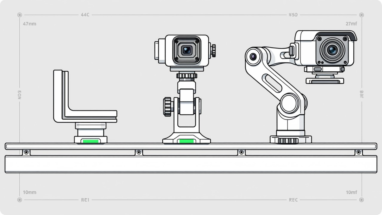
Visual SOP Camera Selection and Mounting
Camera selection for visual SOP is not the same as for product inspection. The s…
Read more → -
Vision Monitoring at the Semiconductor Die Bonder
Semiconductor packaging stations are characterised by high precision, fast cycle…
Read more → -
Wrong-Assembly Alarms Without the False Alarms
The most common reason a visual SOP project fails is not poor recognition — it i…
Read more →
Need specific advice for your production line?
Our engineers can share practical approaches to process error prevention and SOP compliance inspection for your scenario.
Request a free trial plan