
Multi-Camera Alignment
A single camera station needs one calibration. The moment a second camera is added, a second problem appears: each camera is accurate in its own frame, and the two frames differ by a transform nobody has established. That transform has to be built from something both cameras can see, or from a mechanism that carries a known artefact between them. The arithmetic is routine; the difficulty is that when alignment fails, each camera still looks perfectly correct on its own.
Key takeaways
- Individual calibration makes each camera accurate, not the pair consistent.
- Alignment needs a shared reference — there is no way to derive it from the two calibrations.
- Choose a reference that is hard to knock and can be re-checked automatically.
- Alignment failure looks like two correct readings that disagree, so monitor it explicitly.
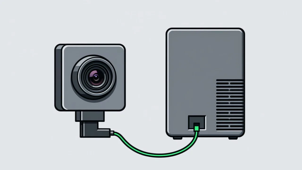
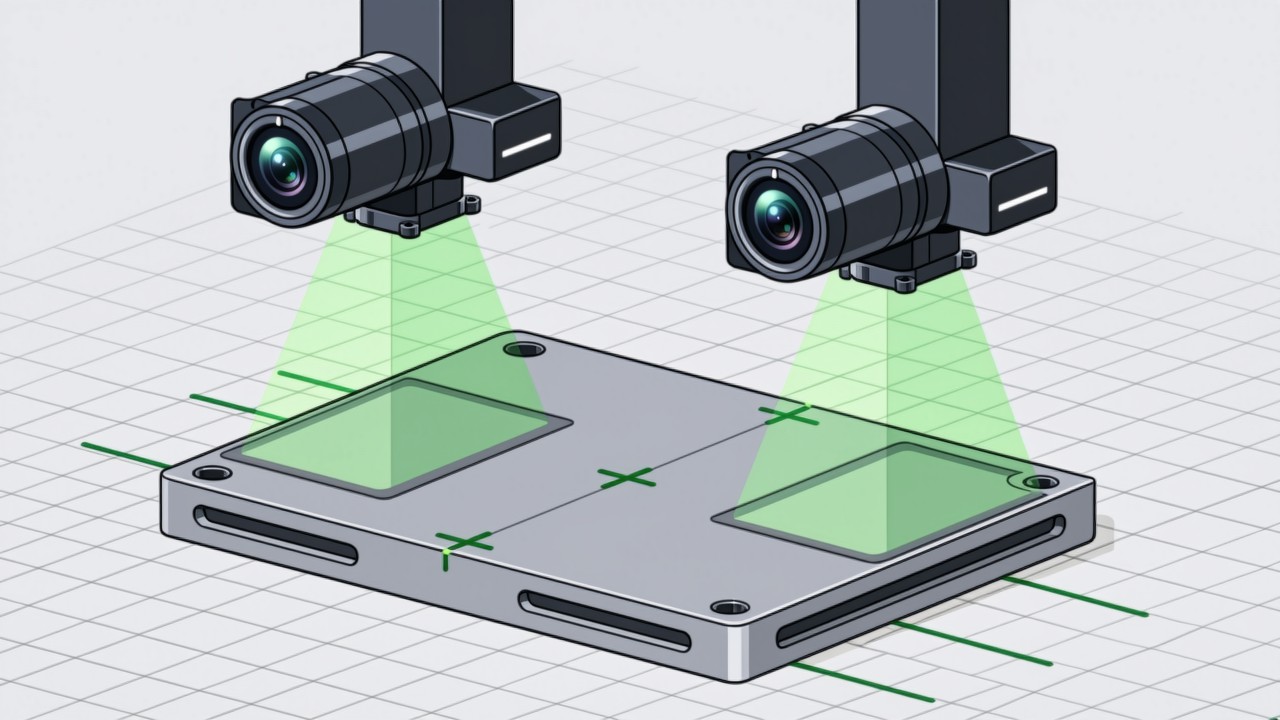
Two cameras can each be calibrated to convert pixels into millimetres perfectly, and still disagree about where a feature is. The reason is that each calibration relates its own camera to the object plane, and says nothing about where the other camera is. If one camera measures the left half of a part and the other the right half, and the criterion is the total length, then the relationship between the two cameras has become part of the measurement whether or not anyone established it.
When alignment is actually needed
- A dimension split across cameras. The feature is larger than one field of view, or its geometry means it can only be seen in two parts.
- Several stations measuring one part. Assembly lines where each station inspects a portion and the results are combined into one record.
- Multiple views of one part. Top, side and end cameras, where the question is whether a hole on one face lines up with a boss on another.
- Any criterion that combines readings. The moment a criterion subtracts one camera's value from another's, alignment is implied, whether it has been done or not.
The converse is worth stating because it saves money. If the cameras have no criteria in common — each looks at its own features, judges independently, and records separately — then no alignment is needed and adding one is pure cost. The test is whether any single judgement uses the output of two cameras. If none does, leave it alone.
What establishes the relation
| Method | How it works | Applies when | Risk |
|---|---|---|---|
| Shared target | One plate imaged by several cameras at once | Fields of view overlap, or a plate can span them | The plate must be large; flatness becomes an error source |
| Shared fiducials | Each camera images the same fixed marks in its own view | No overlap, but common fixed features exist | Move the marks and everything is invalid |
| Via a mechanism | A robot or axis carries a known artefact into each view in turn | Motion is available | The mechanism's repeatability enters the alignment error |
| No alignment | Split the criterion into independent judgements combined in logic | The criterion can be decomposed | Not a risk at all — the cheapest option when it applies |
A planar alignment needs at least three common points, and they must not be collinear. Three points on a line leave the rotation about that line undetermined, so the resulting transform is unconstrained in the direction perpendicular to it. In practice four to eight points are used, spread across the overlap. Collinear points are a common error precisely because the convenient places to put a marker are often in a row — along a rail, or along the front edge of a bench.
Practical notes
- Prefer not to align. If the cross-camera criterion can be restated as independent judgements combined in logic, do that instead. "Total length in range" can often become "left segment in range and right segment in range", at which point the alignment disappears.
- Put the reference where it cannot be hit. A fiducial on the edge of a bench where parts and tools sweep past is a fault waiting to happen. Somewhere recessed costs a little at calibration time and saves a great deal later.
- Add the alignment uncertainty to the tolerance. Alignment error goes straight into the uncertainty of whatever dimension spans the cameras. If the tolerance is ±0.1 mm and the alignment itself carries 0.08 mm, the scheme does not close on paper before anything is built.
- Manage the parameters like a recipe. Alignment values determine whether criteria are met, exactly as exposure and gain do. They need a version, a change record, and a home other than an engineer's laptop.
Common questions about multi-camera alignment
Can cameras with no overlapping view be aligned?
Yes, with a bridge. Use an artefact with a known geometry that appears in each camera in turn — a bar with marks at each end, for example, where each camera sees one mark and the bar is then moved so the marks trade places. The two views share an observed object, which relates the frames. The motion has to be repeatable, because its repeatability becomes part of the alignment error.
Does alignment stay put once it is done?
No. Camera brackets, the bench, and the reference marks can all shift or deform. Thermal expansion does it too: a long bracket changes length enough between a cold morning and a warm afternoon to move two distant cameras measurably relative to each other. Alignment parameters need a re-check mechanism for the same reason calibration does.
Can image stitching software do this automatically?
Feature-based stitching is mature for photographs and dangerous for measurement. Its purpose is a picture that looks continuous, not coordinates that agree with the physical world. The transform it produces is not guaranteed to correspond to real dimensions, or to be the same twice. It is fine for a display an operator reads; for measurement, use a calibration.
Do any of your criteria span two cameras?
Tell us which dimensions have to be judged together and where the cameras sit. We will say whether it can be split, or whether alignment is unavoidable.
Related articles
-
Alarm Fatigue: Why the Floor Turns the System Off
Many visual SOP systems are not beaten by technical problems — they are muted by…
Read more → -
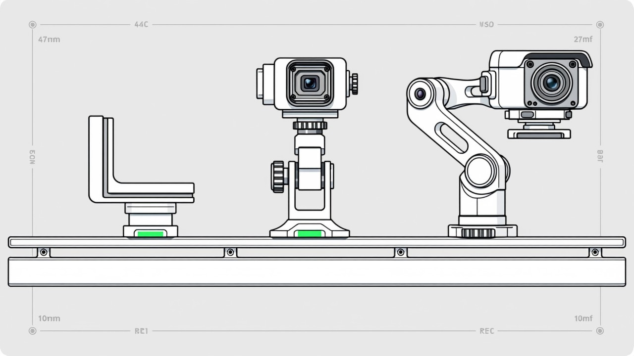
Visual SOP Camera Selection and Mounting
Camera selection for visual SOP is not the same as for product inspection. The s…
Read more → -
Vision Monitoring at the Semiconductor Die Bonder
Semiconductor packaging stations are characterised by high precision, fast cycle…
Read more → -
Wrong-Assembly Alarms Without the False Alarms
The most common reason a visual SOP project fails is not poor recognition — it i…
Read more →
Need specific advice for your production line?
Our engineers can share practical approaches to process error prevention and SOP compliance inspection for your scenario.
Request a free trial plan