
Hand-Eye Calibration
The camera reports pixels; the robot needs millimetres and an angle. The bridge between them is a calibration built from a set of positions where both frames were recorded, and it is the single most important and least visible step in any guidance project. Wrong calibration raises no alarm. The robot moves, the cycle completes, and every result is off by a small amount that varies across the working volume, which is easy to mistake for mechanical error or part tolerance.
Key takeaways
- Calibration points must cover the working volume; a cluster in the middle hides edge errors.
- Checking calibration with the points that built it proves nothing. Keep independent points.
- The transform joins the camera to the robot flange or base, so anything that moves either one invalidates it.
- Eye in hand and eye to hand fail in different ways and need different methods.
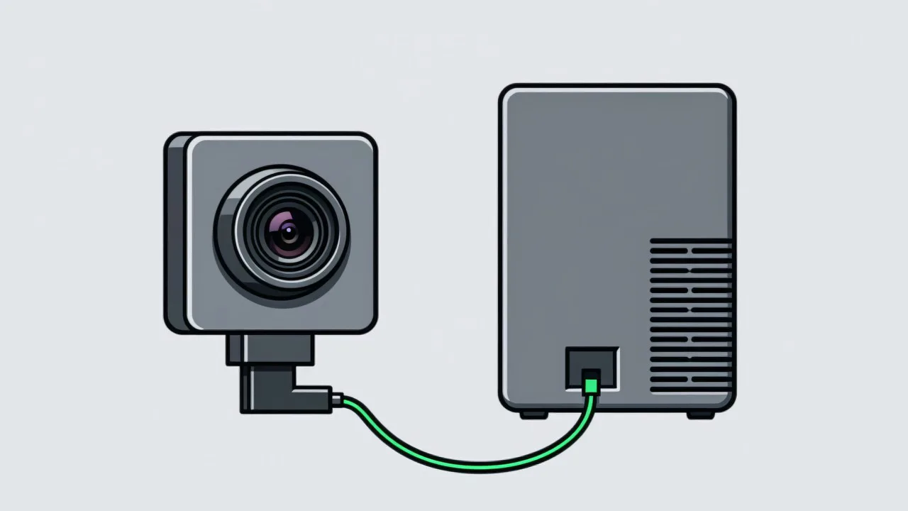
Hand-eye calibration solves a specific arithmetic problem: given a set of positions where the robot reports one coordinate and the camera reports another, find the transformation between the two frames. The mathematics is not difficult. What makes it a project risk is the failure mode. A camera that is out of focus shows up immediately. A calibration that is slightly wrong produces a system that works, in the sense that it does something every cycle, and is wrong in a way that only appears as a persistent bias nobody can explain.
Two configurations
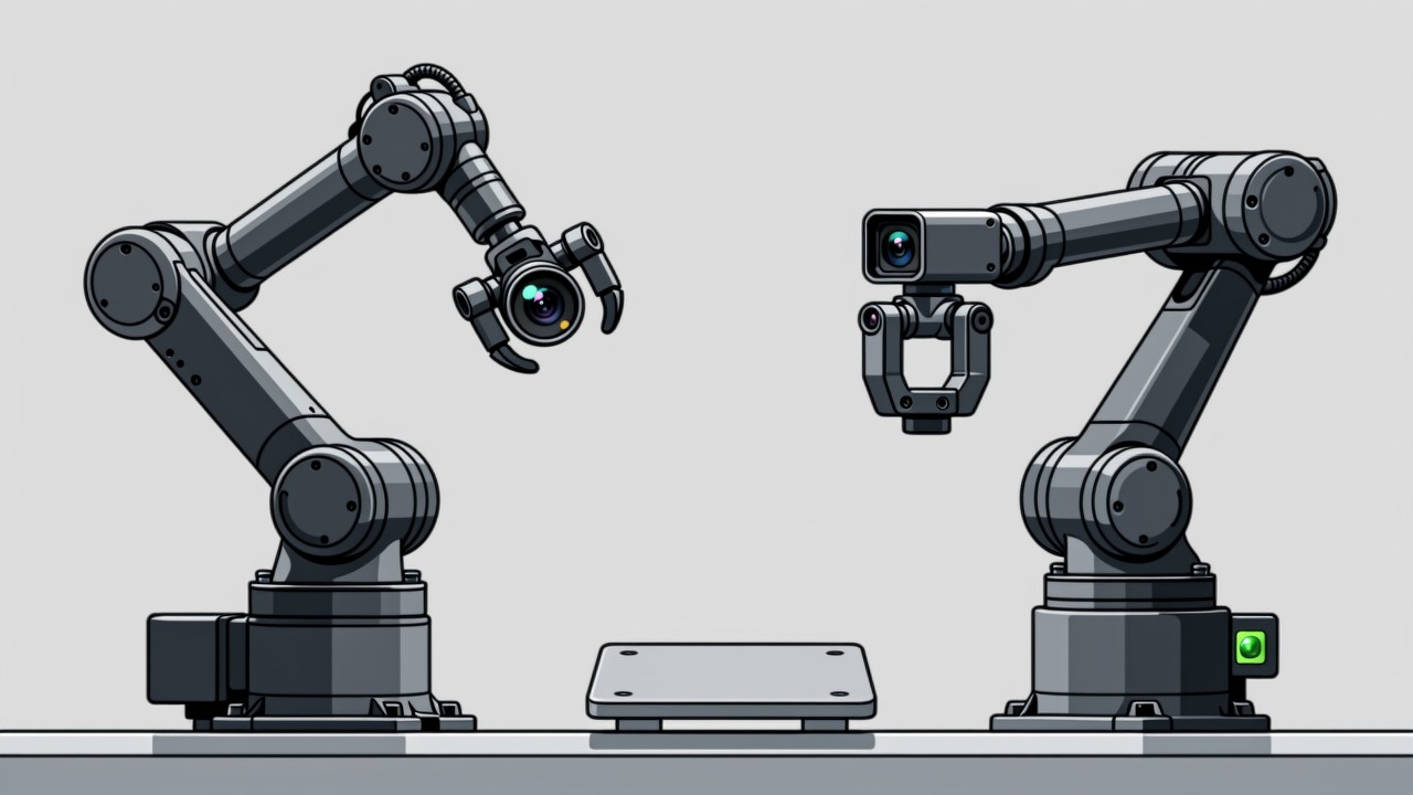
Eye in hand means the camera is mounted on the robot arm and moves with it. The transform being solved is between the camera and the mounting flange. This buys flexibility — the camera can approach, change angle, and trade field of view for resolution — and costs stability, because the imaging conditions change every time the arm moves, and the cable has to survive the motion. Its characteristic failure is a wrong tool offset: the calibration relates to the flange, the calculation uses the tool tip, and a mistake in the tool length shifts every landing point by a fixed amount.
Eye to hand means the camera is fixed on a bracket looking at a work area. The transform is between the camera and the robot base. Lighting and background are easier to control and nothing moves, which is why it is the more common arrangement for a dedicated station. Its characteristic failure is a bracket that has moved — during a relocation, during cleaning, or because somebody pulled the cable run tight and shifted it a millimetre. There is nothing to see, and the calibration is gone.
Choosing the points
The most common mistake is to place all the calibration points in a small cluster at the centre of the view. The fit then matches those points very well, because the model has plenty of freedom to do so, and the error only appears at the edges of the working volume where no constraint was applied. Points should be spread across the entire volume that will be used, including the corners and the mid-points of the edges. The reason is not that the arithmetic needs that many points — it is that only a spread set constrains the fit everywhere it has to be right.
- Distribution matters more than count. Three to five points determine a planar transform; nine to twelve give margin. But twelve points in a cluster are worth less than five spread across the corners and centre.
- Never validate with the calibration points. Fitting and checking on the same data always gives a small residual, which tells you nothing. Take a separate set afterwards — ideally at a different time, by a different person — and record the errors that set produces.
- The calibration artefact is itself a variable. The target, pin or plate must have a stable relationship to the parts. If calibration uses a sharp pin and production uses the real part, whether their apparent centres coincide has to be confirmed separately, not assumed.
- Calibrate at the working height. If the plate is raised or lowered relative to where parts actually sit, a planar calibration picks up an error that varies across the view — invisible at the centre, obvious at the edges.
Verifying the result
Acceptance is not the residual number. Take an independent set of marks, have the system compute where the robot frame says each one is, then drive the robot there and measure the difference with a gauge — pin to pin, or a feeler. Do this at the centre of the volume and at each corner, and record a distribution rather than a single figure. An even distribution inside tolerance is a pass. Accurate in the middle and off at the edges means the model or the point distribution is wrong, not that the robot is imprecise.
Common questions about hand-eye calibration
Are nine points enough?
For planar guidance, yes, provided they are spread out. For guidance in three dimensions, or with the camera at an angle, a planar calibration cannot represent variation along the optical axis, and the symptom is a system that is accurate within a plane and wrong the moment the height changes. That needs a calibration with three dimensional constraints, not more points in a plane.
What accuracy can be achieved?
It depends on camera resolution, field of view, and the robot's own accuracy, and cannot be promised in isolation. One fact that catches people out: a robot's absolute positioning accuracy is usually much worse than its repeatability. If the task is to return to the same position each cycle, repeatability governs. If it is to reach a computed absolute coordinate, absolute accuracy governs, and the two can differ by an order of magnitude. Ask which one applies before quoting a number.
Can the system monitor its own calibration?
Yes, and it is worth setting up. Place a fixed fiducial at a known location, image it at the start of each shift or each start-up, and compare the computed position against the recorded one. A drift in the reading means the calibration has changed. The action costs seconds and converts the hardest fault to diagnose into an explicit alarm.
How far off is your guidance station?
Tell us the robot, the working volume and the landing accuracy you need. We will work out which configuration applies and how to make the calibration maintainable.
Related articles
-
Alarm Fatigue: Why the Floor Turns the System Off
Many visual SOP systems are not beaten by technical problems — they are muted by…
Read more → -
Visual SOP Camera Selection and Mounting
Camera selection for visual SOP is not the same as for product inspection. The s…
Read more → -
Vision Monitoring at the Semiconductor Die Bonder
Semiconductor packaging stations are characterised by high precision, fast cycle…
Read more → -
Wrong-Assembly Alarms Without the False Alarms
The most common reason a visual SOP project fails is not poor recognition — it i…
Read more →
Need specific advice for your production line?
Our engineers can share practical approaches to process error prevention and SOP compliance inspection for your scenario.
Request a free trial plan